An Enduring Symbol of Reliability
P&H Mining Equipment spans more than a century of American and global industrial development.
Founded when the American West was still wild and a horse was a transportation mainstay for country and city folk alike, P&H Mining Equipment today delivers superb and highly reliable mining equipment for the very cost-focused world surface mining industry.
The sun never sets upon P&H drills, shovels, draglines and our allied products deployed to nine of ten surface mines around the world. And through our global network of P&H MinePro Services dealers, that equipment delivers exceptional productivity value through our life cycle management support.
When you see the P&H brand, you see an enduring symbol of quality and service reliability forged over more than a century.
1884
Alonzo Pawling and Henry Harnischfeger join forces on December 1, 1884, starting up a small machine and pattern shop to transform industrial component and device ideas into models and patterns. As word of the craftsmanship of Pawling & Harnischfeger spreads, the partners begin manufacturing components and equipment for knitting, grain-drying, stamping, brewing and brick-making - and they do a great deal of repair work as well.
1887
Pawling & Harnischfeger rebuild and improve upon the design of a damaged overhead crane made by another manufacturer. The safer, more durable crane powered by three electric motors quickly attracts attention and generates orders from factories, utilities and railroad repair shops across the country.
1911
In failing health, Alonzo Pawling decides to sell his interest in the business to his partner, Henry Harnischfeger, who decides to keep the now well-known P&H trademark as the former partnership goes forward as a corporation called “Harnischfeger Corporation.”
1912
Harnischfeger Corporation begins making earth-moving equipment. Trenching machines and wheel loaders are among the first “P&H” digging machines, followed soon after by crawler-mounted digging equipment including backfillers and wheel-type trenchers.
1914
During World War I, Harnischfeger Corporation concentrates on making overhead cranes for the war effort. After the war, development of earthmoving equipment resumes. Harnischfeger engineers design the world’s first gasoline engine-powered dragline. Soon after that, Harnischfeger engineers develop a shovel-type excavator mounted on crawlers.
1930
Co-founder Henry Harnischfeger dies and is succeeded by his son Walter Harnischfeger as president. During the Great Depression P&H struggles but moves forward, converting its cranes and excavators to all-welded design and fabrication for increased strength and efficiency.
1935
Harnischfeger Corporation introduces “Bantamweight” gas-powered excavators with up to ½-cubic-yard capacity. P&H also introduces new Ward-Leonard drive electric excavators.
1942
World War II brings the American economy to full capacity, and Harnischfeger Corporation mass-produces its “P&H” cranes and excavators for the war effort. The firm earns “E” awards from the Navy and Army for efficiency in meeting stepped-up production needs.
1945
Peacetime marks the beginning of a world-wide industrial boom. P&H excavators and overhead and construction cranes contribute in a major way, both in America and in emerging markets worldwide. P&H introduces a new-generation electric mining shovel featuring simpler control components and factory-installed wiring for faster field erection and commissioning.
1946
Harnischfeger Corporation engineers develop “Magnetorque” electro-magnetic brake and control system to replace traditional friction mechanisms for greatly increased digging power and speed. Magnetorque revolutionizes the heavy equipment industry and continues to be used on smaller electric shovels for decades to come.
1952
P&H introduces its largest capacity electric dragline to date - the Model 1855 with up to 10 cubic yards bucket capacity. Magnetorque magnetic clutch system applied to every operating function: digging, hoisting, swinging and propelling. Designed primarily for strip mining, the 1855 brings new standards of performance to the field of large excavators.
1954
P&H rolls out its new Model 1800 electric mining shovel - the latest and largest heavy-duty digging machine in the P&H line with electronic control, centralized AC motor drive, and numerous mechanical improvements.
1959
Harnischfeger Corporation continues to expand its global network of customer support operations by entering into a joint ownership of a new company in Australia, P&H Power Cranes and Shovels, Pty., Ltd. Henry Harnischfeger, grandson of the founder, becomes president and guides Harnischfeger Corporation through significant growth in the 60s and 70s.
1960
P&H shovel maximum dipper capacity reaches 12 cubic yards to help meet growing demand for highly productive taconite and other hard-rock mining excavators.
1962
P&H embarks on formal training programs for personnel engaged in operating and maintaining P&H equipment.
1967
P&H shovel maximum dipper capacity increases to 15 cubic yards.
1969
In a major leap forward, the P&H 2800 electric shovel debuts initially with a 25 cubic yard dipper capacity to help meet growing world demand for coal, iron and copper. P&H 2800 innovations include solid-state electronic control and planetary propel, enabling the new-generation shovel to greatly increase productivity and overall performance.
1973
Walter Harnischfeger dies. Over the previous six decades he led the firm through the Depression and transformed Harnischfeger Corporation into a global leader in the supply of equipment and support to the mining industry.
1976
P&H increases maximum dipper capacity on its 2800-class shovel to 40 cubic yards. More significant, P&H introduces “Electrotorque” solid-state control for DC motors - a single-stage controlled power manipulation that delivers an abundant adjustable-voltage DC power supply, along with easy-to-understand control troubleshooting, maintenance and repair.
1984
Harnischfeger Corporation reaches 100 consecutive years of product quality and service excellence on behalf of industry.
1988
The company acquires the Page Engineering walking dragline product line and begins modernizing the line for increased performance value.
1991
Harnischfeger Corporation acquires the Gardner-Denver line of large rotary blast hole drills and proceeds to implement needed upgrades for increased performance value. Also in 1991, the P&H 4100-class shovel line rolls out to help mines 3-pass-load 240-ton haul trucks. The 4100 features 85-ton dipper payloads and numerous ease-of-maintenance features including modular components - improvements resulting from growing consultation with mine managers.
1994
P&H 120A blast hole drill rolls out with numerous performance-boosting improvements.
1995
The underground mining equipment supplier, Joy Mining Machinery, joins P&H Mining Equipment in the holding company known as Harnischfeger Industries, Inc.
1996
P&H Mining Equipment launches its global network of regional P&H MinePro Services centers to provide local service and distribution support for surface mine customers. Also, the 4100 shovel evolves into the 4100A, featuring DC digital “Electrotorque Plus” drive for faster digging cycles due to optimized peak horsepower, and improved information systems for the shovel operator and maintenance team.
1997
P&H 4100TS rolls out and quickly gains a foothold in the Canadian oil sands as a high-performance loading tool.
1999
P&H Mining Equipment introduces the Bigger, Faster, Smarter P&H 4100XPB - a versatile loading tool tailored to mines utilizing 240-ton, 320-ton and 360-ton haulers. Bigger payloads of 100-plus tons, faster cycle times, and smarter control systems for optimized digging performance and increased productivity. P&H Mining Equipment parent company Harnischfeger Industries, Inc. files for Chapter 11 financial restructuring stemming from sister firm Beloit Corporation (papermaking machinery) severe difficulties in wake of Asian currency devaluation crisis.
2001
In a collaborative effort with oil sands mines, P&H Mining Equipment introduces the P&H 4100BOSS, a higher-performance successor to the well-regarded P&H 4100TS. Parent company “Harnischfeger Industries, Inc.” emerges from Chapter 11 financial restructuring and undergoes a name change to “Joy Global Inc.”
Showing posts with label Crane. Show all posts
Showing posts with label Crane. Show all posts
Saturday, January 24, 2009
Wednesday, January 16, 2008
What is Crane?
A crane is a mechanical lifting device equipped with a winder, wire ropes and sheaves that can be used both to lift and lower materials and to move them horizontally. It uses one or more simple machines to create mechanical advantage and thus move loads beyond the normal capability of a human. Cranes are commonly employed in the transport industry for the loading and unloading of freight; in the construction industry for the movement of materials; and in the manufacturing industry for the assembling of heavy equipment.
Overview
The first cranes were invented by the Ancient Greeks and were powered by men or beasts-of-burden, such as donkeys. These cranes were used for the construction of tall buildings. Larger cranes were later developed, employing the use of human treadwheels, permitting the lifting of heavier weights. In the High Middle Ages, harbour cranes were introduced to load and unload ships and assist with their construction – some were built into stone towers for extra strength and stability. The earliest cranes were constructed from wood, but cast iron and steel took over with the coming of the Industrial Revolution.go away
For many centuries, power was supplied by the physical exertion of men or animals, although hoists in watermills and windmills could be driven by the harnessed natural power. The first 'mechanical' power was provided by steam engines, the earliest steam crane being introduced in the 18th or 19th century, with many remaining in use well into the late 20th century. Modern cranes usually use internal combustion engines or electric motors and hydraulic systems to provide a much greater lifting capability than was previously possible, although manual cranes are still utilised where the provision of power would be uneconomic.
Cranes exist in an enormous variety of forms – each tailored to a specific use. Sizes range from the smallest jib cranes, used inside workshops, to the tallest tower cranes, used for constructing high buildings, and the largest floating cranes, used to build oil rigs and salvage sunken ships.
This article also covers lifting machines that do not strictly fit the above definition of a crane, but are generally known as cranes, such as stacker cranes and loader cranes.
History of cranes
Ancient Greek cranes
The crane for lifting heavy loads was invented by the ancient Greeks in the late 6th century BC.[1] The archaeological record shows that no later than c.515 BC distinctive cuttings for both lifting tongs and lewis irons begin to appear on stone blocks of Greek temples. Since these holes point at the use of a lifting device, and since they are to be found either above the centre of gravity of the block, or in pairs equidistant from a point over the centre of gravity, they are regarded by archaeologists as the positive evidence required for the existence of the crane.[1]
The introduction of the winch and pulley hoist soon lead to a widespread replacement of ramps as the main means of vertical motion. For the next two hundred years, Greek building sites witnessed a sharp drop in the weights handled, as the new lifting technique made the use of several smaller stones more practical than of fewer larger ones. In contrast to the archaic period with its tendency to ever-increasing block sizes, Greek temples of the classical age like the Parthenon invariably featured stone blocks weighing less than 15-20 tons. Also, the practice of erecting large monolithic columns was practically abandoned in favour of using several column drums.[2]
Although the exact circumstances of the shift from the ramp to the crane technology remain unclear, it has been argued that the volatile social and political conditions of Greece were more suitable to the employment of small, professional construction teams than of large bodies of unskilled labour, making the crane more preferable to the Greek polis than the more labour-intensive ramp which had been the norm in the autocratic societies of Egypt or Assyria.[2]
The first unequivocal literary evidence for the existence of the compound pulley system appears in the Mechanical Problems (Mech. 18, 853a32-853b13) attributed to Aristotle (384-322 BC), but perhaps composed at a slightly later date. Around the same time, block sizes at Greek temples began to match their archaic predecessors again, indicating that the more sophisticated compound pulley must have found its way to Greek construction sites by then.[3]
Ancient Roman cranes

Reconstruction of a 10.4m high Roman Polyspastos at Bonn, Germany (I)

Reconstruction of a 10.4m high Roman Polyspastos at Bonn, Germany (II)
The heyday of crane in ancient times came under the Roman Empire, when construction activity soared and buildings reached enormous dimensions. The Romans adopted the Greek crane and developed it further. We are relatively well informed about their lifting techniques thanks to rather lengthy accounts by the engineers Vitruvius (De Architectura 10.2, 1-10) and Heron of Alexandria (Mechanica 3.2-5). There are also two surviving reliefs of Roman treadwheel cranes offering pictorial evidence, with the Haterii tombstone from the late first century AD being particularly detailed.
The simplest Roman crane, the Trispastos, consisted of a single-beam jib, a winch, a rope, and a block containing three pulleys. Having thus a mechanical advantage of 3:1, it has been calculated that a single man working the winch could raise 150 kg (3 pulleys x 50 kg = 150), assuming that 50 kg represent the maximum effort a man can exert over a longer time period. Heavier crane types featured five pulleys (Pentaspastos) or, in case of the largest one, a set of three by five pulleys (Polyspastos) and came with two, three or four masts, depending on the maximum load. The Polyspastos, when worked by four men at both sides of the winch, could already lift 3000 kg (3 ropes x 5 pulleys x 4 men x 50 kg = 3000 kg). In case the winch was replaced by a treadwheel, the maximum load even doubled to 6000 kg at only half the crew, since the treadwheel possesses a much bigger mechanical advantage due to its larger diameter. This meant that, in comparison to the construction of the Egyptian Pyramids, where about 50 men were needed to move a 2.5 ton stone block up the ramp (50 kg per person), the lifting capability of the Roman Polyspastos proved to be 60 times higher (3000 kg per person).[4]
However, numerous extant Roman buildings which feature much heavier stone blocks than those handled by the Polyspastos indicate that the overall lifting capability of the Romans went far beyond that of any single crane. At the temple of Jupiter at Baalbek, for incidence, the architraves blocks weigh up to 60 tons each, and the corner cornices blocks even over 100 tons, all of them raised to a height of ca. 19 m above the ground.[3] In Rome, the capital block of Trajan's Column weighs 53.3 tons which had to be lifted at a height of ca. 34 m.[5]
It is assumed that Roman engineers accomplished lifting these extraordinary weights by two measures: First, as suggested by Heron, a lifting tower was set up, whose four masts were arranged in the shape of a quadrangle with parallel sides, not unlike a siege tower, but with the column in the middle of the structure (Mechanica 3.5).[6] Second, a multitude of capstans were placed on the ground around the tower, for, although having a lower leverage ratio than treadwheels, capstans could be set up in higher numbers and run by more men (and, moreover, by draught animals).[7] This use of multiple capstans is also described by Ammianus Marcellinus (17.4.15) in connection with the lifting of the Lateranense obelisk in the Circus Maximus (ca. 357 AD). The maximum lifting capability of a single capstan can be established by the number of lewis iron holes bored into the monolith. In case of the Baalbek architrave blocks, which weigh between 55 and 60 tons, eight extant holes suggest an allowance of 7.5 ton per lewis iron, that is per capstan.[8] Lifting such heavy weights in a concerted action required a great amount of coordination between the work groups applying the force to the capstans.
Medieval cranes

Small-scale reconstruction of the medieval gantry crane at Brugge harbor

The Kraanplein ("Crane Square") at Brugge is glimpsed in this portrait of 1551 by Pieter Pourbus

Medieval port crane with building overhanging in the former Hanse town of Danzig.
During the High Middle Ages the treadwheel crane was reintroduced on a large scale after the technology had fallen into disuse in western Europe with the demise of the Western Roman Empire.[9] The earliest reference to a treadwheel (magna rota) reappears in archival literature in France about 1225,[10] followed by an illuminated depiction in a manuscript of probably also French origin dating to 1240.[9] In navigation, the earliest uses of harbor cranes are documented for Utrecht in 1244, Antwerp in 1263, Brugge in 1288 and Hamburg in 1291,[11] while in England the treadwheel is not recorded before 1331.[12]
Generally, vertical transport was done safer and cheaper by cranes than by customary methods. Typical areas of application were harbors, mines, and, in particular, building sites where the treadwheel crane played a pivotal role in the construction of the lofty Gothic cathedrals. Nevertheless, both archival and pictorial sources of the time suggest that newly introduced machines like treadwheels or wheelbarrows did not completely replace more labor-intensive methods like ladders, hods and handbarrows. Rather, old and new machinery continued to coexist on medieval construction sites[13] and harbors.[11]
Apart from treadwheels, medieval depictions also show cranes to be powered manually by windlasses with radiating spokes, cranks and by the 15th century also by windlasses shaped like a ship's wheel. To smooth out irregularities of impulse and get over 'dead-spots' in the lifting process flywheels are known to be in use as early as 1123.[14]
Origins
The exact process by which the treadwheel crane was reintroduced is not recorded,[10] although its return to construction sites has undoubtedly to be viewed in close connection with the simultaneous rise of Gothic architecture. The reappearance of the treadwheel crane may have resulted from a technological development of the windlass from which the treadwheel structurally and mechanically evolved. Alternatively, the medieval treadwheel may represent a deliberate reinvention of its Roman counterpart drawn from Vitruvius' De architectura which was available in many monastic libraries. Its reintroduction may have been inspired, as well, by the observation of the labor-saving qualities of the waterwheel with which early treadwheels shared many structural similarities.[12]
Structure and placement
The medieval treadwheel was a large wooden wheel turning around a central shaft with a treadway wide enough for two workers walking side by side. While the earlier 'compass-arm' wheel had spokes directly driven into the central shaft, the more advanced 'clasp-arm' type featured arms arranged as chords to the wheel rim,[15] giving the possibility of using a thinner shaft and providing thus a greater mechanical advantage.[16]
Contrary to a popularly held belief, cranes on medieval building sites were neither placed on the extremely lightweight scaffolding used at the time nor on the thin walls of the Gothic churches which were incapable of supporting the weight of both hoisting machine and load. Rather, cranes were placed in the initial stages of construction on the ground, often within the building. When a new floor was completed, and massive tie beams of the roof connected the walls, the crane was dismantled and reassembled on the roof beams from where it was moved from bay to bay during construction of the vaults.[17] Thus, the crane ‘grew’ and ‘wandered’ with the building with the result that today all extant construction cranes in England are found in church towers above the vaulting and below the roof, where they remained after building construction for bringing material for repairs aloft.[18]
Less frequently, medieval illuminations also show cranes mounted on the outside of walls with the stand of the machine secured to putlogs.[19]
Mechanics and operation
Tower crane at the inland harbour of Trier from 1413.
In contrast to modern cranes, medieval cranes and hoists - much like their counterparts in Greece and Rome[20] - were primarily capable of a vertical lift, and not used to move loads for a considerable distance horizontally as well.[17] Accordingly, lifting work was organized at the workplace in a different way than today. In building construction, for example, it is assumed that the crane lifted the stone blocks either from the bottom directly into place,[17] or from a place opposite the centre of the wall from where it could deliver the blocks for two teams working at each end of the wall.[20] Additionally, the crane master who usually gave orders at the treadwheel workers from outside the crane was able to manipulate the movement laterally by a small rope attached to the load.[21] Slewing cranes which allowed a rotation of the load and were thus particularly suited for dockside work appeared as early as 1340.[22] While ashlar blocks were directly lifted by sling, lewis or devil's clamp (German Teufelskralle), other objects were placed before in containers like pallets, baskets, wooden boxes or barrels.[23]
It is noteworthy that medieval cranes rarely featured ratchets or brakes to forestall the load from running backward.[24] This curious absence is explained by the high friction force exercised by medieval treadwheels which normally prevented the wheel from accelerating beyond control.[21]
Harbor cranes

Beyond the modern warship stands a crane constructed in 1742, used for mounting masts to large sailing vessels. Copenhagen, Denmark
According to the “present state of knowledge” unknown in antiquity, stationary harbor cranes are considered a new development of the Middle Ages.[11] The typical harbor crane was a pivoting structure equipped with double treadwheels. These cranes were placed docksides for the loading and unloading of cargo where they replaced or complemented older lifting methods like see-saws, winches and yards.[11]
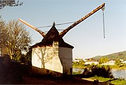
Two different types of harbor cranes can be identified with a varying geographical distribution: While gantry cranes which pivoted on a central vertical axle were commonly found at the Flemish and Dutch coastside, German sea and inland harbors typically featured tower cranes where the windlass and treadwheels were situated in a solid tower with only jib arm and roof rotating.[25] Interestingly, dockside cranes were not adopted in the Mediterranean region and the highly developed Italian ports where authorities continued to rely on the more labor-intensive method of unloading goods by ramps beyond the Middle Ages.[26]
Unlike construction cranes where the work speed was determined by the relatively slow progress of the masons, harbor cranes usually featured double treadwheels to speed up loading. The two treadwheels whose diameter is estimated to be 4 m or larger were attached to each side of the axle and rotated together.[11] Today, according to one survey, fifteen treadwheel harbor cranes from pre-industrial times are still extant throughout Europe.[27] Beside these stationary cranes, floating cranes which could be flexibly deployed in the whole port basin came into use by the 14th century.[25]
Mechanical principles

Cranes helping to construct a tower block in Melbourne, Australia
There are two major considerations that are taken into account in the design of cranes. The first is that the crane must be able to lift a load of a specified weight and the second is that the crane must remain stable and not topple over when the load is lifted and moved to another location.
Lifting capacity
Cranes illustrate the use of one or more simple machines to create mechanical advantage.
The lever. A balance crane contains a horizontal beam (the lever) pivoted about a point called the fulcrum. The principle of the lever allows a heavy load attached to the shorter end of the beam to be lifted by a smaller force applied in the opposite direction to the longer end of the beam. The ratio of the load's weight to the applied force is equal to the ratio of the lengths of the longer arm and the shorter arm, and is called the mechanical advantage.
The pulley. A jib crane contains a tilted strut (the jib) that supports a fixed pulley block. Cables are wrapped multiple times round the fixed block and round another block attached to the load. When the free end of the cable is pulled by hand or by a winding machine, the pulley system delivers a force to the load that is equal to the applied force multiplied by the number of lengths of cable passing between the two blocks. This number is the mechanical advantage.
The hydraulic cylinder. This can be used directly to lift the load (as with a HIAB), or indirectly to move the jib or beam that carries another lifting device.

Tower Crane constructing a building in Kansas City
Cranes, like all machines, obey the principle of conservation of energy. This means that the energy delivered to the load cannot exceed the energy put into the machine. For example, if a pulley system multiplies the applied force by ten, then the load moves only one tenth as far as the applied force. Since energy is proportional to force multiplied by distance, the output energy is kept roughly equal to the input energy (in practice slightly less, because some energy is lost to friction and other inefficiencies).
Stability of crane
In order for a crane to be stable, the sum of all moments about any point such as the base of the crane must equate to zero. In practice, the magnitude of load that is permitted to be lifted (called the "rated load" in the US) is some value less than the load that will cause the crane to tip.
Under US standards for mobile cranes, the stability-limited rated load for a crawler crane is 75% of the tipping load. The stability-limited rated load for a mobile crane supported on outriggers is 85% of the tipping load.
For stationary pedistal or kingpost mounted cranes, the moment created by the boom, jib, and load is resisted by the pedistal base or kingpost. Stress within the base must be less than the yield stress of the material or the crane will fail.
Overview
The first cranes were invented by the Ancient Greeks and were powered by men or beasts-of-burden, such as donkeys. These cranes were used for the construction of tall buildings. Larger cranes were later developed, employing the use of human treadwheels, permitting the lifting of heavier weights. In the High Middle Ages, harbour cranes were introduced to load and unload ships and assist with their construction – some were built into stone towers for extra strength and stability. The earliest cranes were constructed from wood, but cast iron and steel took over with the coming of the Industrial Revolution.go away
For many centuries, power was supplied by the physical exertion of men or animals, although hoists in watermills and windmills could be driven by the harnessed natural power. The first 'mechanical' power was provided by steam engines, the earliest steam crane being introduced in the 18th or 19th century, with many remaining in use well into the late 20th century. Modern cranes usually use internal combustion engines or electric motors and hydraulic systems to provide a much greater lifting capability than was previously possible, although manual cranes are still utilised where the provision of power would be uneconomic.
Cranes exist in an enormous variety of forms – each tailored to a specific use. Sizes range from the smallest jib cranes, used inside workshops, to the tallest tower cranes, used for constructing high buildings, and the largest floating cranes, used to build oil rigs and salvage sunken ships.
This article also covers lifting machines that do not strictly fit the above definition of a crane, but are generally known as cranes, such as stacker cranes and loader cranes.
History of cranes
Ancient Greek cranes
The crane for lifting heavy loads was invented by the ancient Greeks in the late 6th century BC.[1] The archaeological record shows that no later than c.515 BC distinctive cuttings for both lifting tongs and lewis irons begin to appear on stone blocks of Greek temples. Since these holes point at the use of a lifting device, and since they are to be found either above the centre of gravity of the block, or in pairs equidistant from a point over the centre of gravity, they are regarded by archaeologists as the positive evidence required for the existence of the crane.[1]
The introduction of the winch and pulley hoist soon lead to a widespread replacement of ramps as the main means of vertical motion. For the next two hundred years, Greek building sites witnessed a sharp drop in the weights handled, as the new lifting technique made the use of several smaller stones more practical than of fewer larger ones. In contrast to the archaic period with its tendency to ever-increasing block sizes, Greek temples of the classical age like the Parthenon invariably featured stone blocks weighing less than 15-20 tons. Also, the practice of erecting large monolithic columns was practically abandoned in favour of using several column drums.[2]
Although the exact circumstances of the shift from the ramp to the crane technology remain unclear, it has been argued that the volatile social and political conditions of Greece were more suitable to the employment of small, professional construction teams than of large bodies of unskilled labour, making the crane more preferable to the Greek polis than the more labour-intensive ramp which had been the norm in the autocratic societies of Egypt or Assyria.[2]
The first unequivocal literary evidence for the existence of the compound pulley system appears in the Mechanical Problems (Mech. 18, 853a32-853b13) attributed to Aristotle (384-322 BC), but perhaps composed at a slightly later date. Around the same time, block sizes at Greek temples began to match their archaic predecessors again, indicating that the more sophisticated compound pulley must have found its way to Greek construction sites by then.[3]
Ancient Roman cranes

Reconstruction of a 10.4m high Roman Polyspastos at Bonn, Germany (I)

Reconstruction of a 10.4m high Roman Polyspastos at Bonn, Germany (II)
The heyday of crane in ancient times came under the Roman Empire, when construction activity soared and buildings reached enormous dimensions. The Romans adopted the Greek crane and developed it further. We are relatively well informed about their lifting techniques thanks to rather lengthy accounts by the engineers Vitruvius (De Architectura 10.2, 1-10) and Heron of Alexandria (Mechanica 3.2-5). There are also two surviving reliefs of Roman treadwheel cranes offering pictorial evidence, with the Haterii tombstone from the late first century AD being particularly detailed.
The simplest Roman crane, the Trispastos, consisted of a single-beam jib, a winch, a rope, and a block containing three pulleys. Having thus a mechanical advantage of 3:1, it has been calculated that a single man working the winch could raise 150 kg (3 pulleys x 50 kg = 150), assuming that 50 kg represent the maximum effort a man can exert over a longer time period. Heavier crane types featured five pulleys (Pentaspastos) or, in case of the largest one, a set of three by five pulleys (Polyspastos) and came with two, three or four masts, depending on the maximum load. The Polyspastos, when worked by four men at both sides of the winch, could already lift 3000 kg (3 ropes x 5 pulleys x 4 men x 50 kg = 3000 kg). In case the winch was replaced by a treadwheel, the maximum load even doubled to 6000 kg at only half the crew, since the treadwheel possesses a much bigger mechanical advantage due to its larger diameter. This meant that, in comparison to the construction of the Egyptian Pyramids, where about 50 men were needed to move a 2.5 ton stone block up the ramp (50 kg per person), the lifting capability of the Roman Polyspastos proved to be 60 times higher (3000 kg per person).[4]
However, numerous extant Roman buildings which feature much heavier stone blocks than those handled by the Polyspastos indicate that the overall lifting capability of the Romans went far beyond that of any single crane. At the temple of Jupiter at Baalbek, for incidence, the architraves blocks weigh up to 60 tons each, and the corner cornices blocks even over 100 tons, all of them raised to a height of ca. 19 m above the ground.[3] In Rome, the capital block of Trajan's Column weighs 53.3 tons which had to be lifted at a height of ca. 34 m.[5]
It is assumed that Roman engineers accomplished lifting these extraordinary weights by two measures: First, as suggested by Heron, a lifting tower was set up, whose four masts were arranged in the shape of a quadrangle with parallel sides, not unlike a siege tower, but with the column in the middle of the structure (Mechanica 3.5).[6] Second, a multitude of capstans were placed on the ground around the tower, for, although having a lower leverage ratio than treadwheels, capstans could be set up in higher numbers and run by more men (and, moreover, by draught animals).[7] This use of multiple capstans is also described by Ammianus Marcellinus (17.4.15) in connection with the lifting of the Lateranense obelisk in the Circus Maximus (ca. 357 AD). The maximum lifting capability of a single capstan can be established by the number of lewis iron holes bored into the monolith. In case of the Baalbek architrave blocks, which weigh between 55 and 60 tons, eight extant holes suggest an allowance of 7.5 ton per lewis iron, that is per capstan.[8] Lifting such heavy weights in a concerted action required a great amount of coordination between the work groups applying the force to the capstans.
Medieval cranes

Small-scale reconstruction of the medieval gantry crane at Brugge harbor

The Kraanplein ("Crane Square") at Brugge is glimpsed in this portrait of 1551 by Pieter Pourbus

Medieval port crane with building overhanging in the former Hanse town of Danzig.
During the High Middle Ages the treadwheel crane was reintroduced on a large scale after the technology had fallen into disuse in western Europe with the demise of the Western Roman Empire.[9] The earliest reference to a treadwheel (magna rota) reappears in archival literature in France about 1225,[10] followed by an illuminated depiction in a manuscript of probably also French origin dating to 1240.[9] In navigation, the earliest uses of harbor cranes are documented for Utrecht in 1244, Antwerp in 1263, Brugge in 1288 and Hamburg in 1291,[11] while in England the treadwheel is not recorded before 1331.[12]
Generally, vertical transport was done safer and cheaper by cranes than by customary methods. Typical areas of application were harbors, mines, and, in particular, building sites where the treadwheel crane played a pivotal role in the construction of the lofty Gothic cathedrals. Nevertheless, both archival and pictorial sources of the time suggest that newly introduced machines like treadwheels or wheelbarrows did not completely replace more labor-intensive methods like ladders, hods and handbarrows. Rather, old and new machinery continued to coexist on medieval construction sites[13] and harbors.[11]
Apart from treadwheels, medieval depictions also show cranes to be powered manually by windlasses with radiating spokes, cranks and by the 15th century also by windlasses shaped like a ship's wheel. To smooth out irregularities of impulse and get over 'dead-spots' in the lifting process flywheels are known to be in use as early as 1123.[14]
Origins
The exact process by which the treadwheel crane was reintroduced is not recorded,[10] although its return to construction sites has undoubtedly to be viewed in close connection with the simultaneous rise of Gothic architecture. The reappearance of the treadwheel crane may have resulted from a technological development of the windlass from which the treadwheel structurally and mechanically evolved. Alternatively, the medieval treadwheel may represent a deliberate reinvention of its Roman counterpart drawn from Vitruvius' De architectura which was available in many monastic libraries. Its reintroduction may have been inspired, as well, by the observation of the labor-saving qualities of the waterwheel with which early treadwheels shared many structural similarities.[12]
Structure and placement
The medieval treadwheel was a large wooden wheel turning around a central shaft with a treadway wide enough for two workers walking side by side. While the earlier 'compass-arm' wheel had spokes directly driven into the central shaft, the more advanced 'clasp-arm' type featured arms arranged as chords to the wheel rim,[15] giving the possibility of using a thinner shaft and providing thus a greater mechanical advantage.[16]
Contrary to a popularly held belief, cranes on medieval building sites were neither placed on the extremely lightweight scaffolding used at the time nor on the thin walls of the Gothic churches which were incapable of supporting the weight of both hoisting machine and load. Rather, cranes were placed in the initial stages of construction on the ground, often within the building. When a new floor was completed, and massive tie beams of the roof connected the walls, the crane was dismantled and reassembled on the roof beams from where it was moved from bay to bay during construction of the vaults.[17] Thus, the crane ‘grew’ and ‘wandered’ with the building with the result that today all extant construction cranes in England are found in church towers above the vaulting and below the roof, where they remained after building construction for bringing material for repairs aloft.[18]
Less frequently, medieval illuminations also show cranes mounted on the outside of walls with the stand of the machine secured to putlogs.[19]
Mechanics and operation

Tower crane at the inland harbour of Trier from 1413.
In contrast to modern cranes, medieval cranes and hoists - much like their counterparts in Greece and Rome[20] - were primarily capable of a vertical lift, and not used to move loads for a considerable distance horizontally as well.[17] Accordingly, lifting work was organized at the workplace in a different way than today. In building construction, for example, it is assumed that the crane lifted the stone blocks either from the bottom directly into place,[17] or from a place opposite the centre of the wall from where it could deliver the blocks for two teams working at each end of the wall.[20] Additionally, the crane master who usually gave orders at the treadwheel workers from outside the crane was able to manipulate the movement laterally by a small rope attached to the load.[21] Slewing cranes which allowed a rotation of the load and were thus particularly suited for dockside work appeared as early as 1340.[22] While ashlar blocks were directly lifted by sling, lewis or devil's clamp (German Teufelskralle), other objects were placed before in containers like pallets, baskets, wooden boxes or barrels.[23]
It is noteworthy that medieval cranes rarely featured ratchets or brakes to forestall the load from running backward.[24] This curious absence is explained by the high friction force exercised by medieval treadwheels which normally prevented the wheel from accelerating beyond control.[21]
Harbor cranes

Beyond the modern warship stands a crane constructed in 1742, used for mounting masts to large sailing vessels. Copenhagen, Denmark
According to the “present state of knowledge” unknown in antiquity, stationary harbor cranes are considered a new development of the Middle Ages.[11] The typical harbor crane was a pivoting structure equipped with double treadwheels. These cranes were placed docksides for the loading and unloading of cargo where they replaced or complemented older lifting methods like see-saws, winches and yards.[11]
Two different types of harbor cranes can be identified with a varying geographical distribution: While gantry cranes which pivoted on a central vertical axle were commonly found at the Flemish and Dutch coastside, German sea and inland harbors typically featured tower cranes where the windlass and treadwheels were situated in a solid tower with only jib arm and roof rotating.[25] Interestingly, dockside cranes were not adopted in the Mediterranean region and the highly developed Italian ports where authorities continued to rely on the more labor-intensive method of unloading goods by ramps beyond the Middle Ages.[26]
Unlike construction cranes where the work speed was determined by the relatively slow progress of the masons, harbor cranes usually featured double treadwheels to speed up loading. The two treadwheels whose diameter is estimated to be 4 m or larger were attached to each side of the axle and rotated together.[11] Today, according to one survey, fifteen treadwheel harbor cranes from pre-industrial times are still extant throughout Europe.[27] Beside these stationary cranes, floating cranes which could be flexibly deployed in the whole port basin came into use by the 14th century.[25]
Mechanical principles

Cranes helping to construct a tower block in Melbourne, Australia
There are two major considerations that are taken into account in the design of cranes. The first is that the crane must be able to lift a load of a specified weight and the second is that the crane must remain stable and not topple over when the load is lifted and moved to another location.
Lifting capacity
Cranes illustrate the use of one or more simple machines to create mechanical advantage.
The lever. A balance crane contains a horizontal beam (the lever) pivoted about a point called the fulcrum. The principle of the lever allows a heavy load attached to the shorter end of the beam to be lifted by a smaller force applied in the opposite direction to the longer end of the beam. The ratio of the load's weight to the applied force is equal to the ratio of the lengths of the longer arm and the shorter arm, and is called the mechanical advantage.
The pulley. A jib crane contains a tilted strut (the jib) that supports a fixed pulley block. Cables are wrapped multiple times round the fixed block and round another block attached to the load. When the free end of the cable is pulled by hand or by a winding machine, the pulley system delivers a force to the load that is equal to the applied force multiplied by the number of lengths of cable passing between the two blocks. This number is the mechanical advantage.
The hydraulic cylinder. This can be used directly to lift the load (as with a HIAB), or indirectly to move the jib or beam that carries another lifting device.

Tower Crane constructing a building in Kansas City
Cranes, like all machines, obey the principle of conservation of energy. This means that the energy delivered to the load cannot exceed the energy put into the machine. For example, if a pulley system multiplies the applied force by ten, then the load moves only one tenth as far as the applied force. Since energy is proportional to force multiplied by distance, the output energy is kept roughly equal to the input energy (in practice slightly less, because some energy is lost to friction and other inefficiencies).
Stability of crane
In order for a crane to be stable, the sum of all moments about any point such as the base of the crane must equate to zero. In practice, the magnitude of load that is permitted to be lifted (called the "rated load" in the US) is some value less than the load that will cause the crane to tip.
Under US standards for mobile cranes, the stability-limited rated load for a crawler crane is 75% of the tipping load. The stability-limited rated load for a mobile crane supported on outriggers is 85% of the tipping load.
For stationary pedistal or kingpost mounted cranes, the moment created by the boom, jib, and load is resisted by the pedistal base or kingpost. Stress within the base must be less than the yield stress of the material or the crane will fail.
Subscribe to:
Posts (Atom)